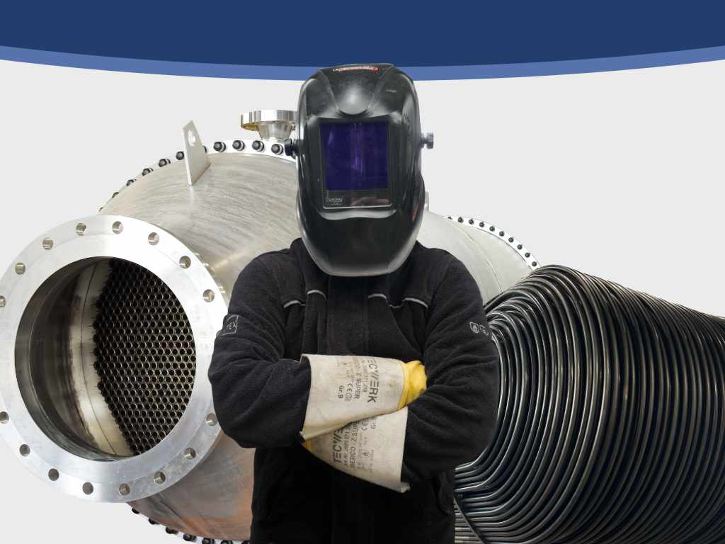
Backed by tens of thousands of heat exchangers manufactured since 1958, SAG capitalizes on its technical know-how and stands as a key player in the design and fabrication of process equipment.
Jean-Maurice Hannard
Business Unit Manager
Visit our materials page
Visit our dedicated page to learn more about materials used in bespoke tubular heat exchangers designs.
Click here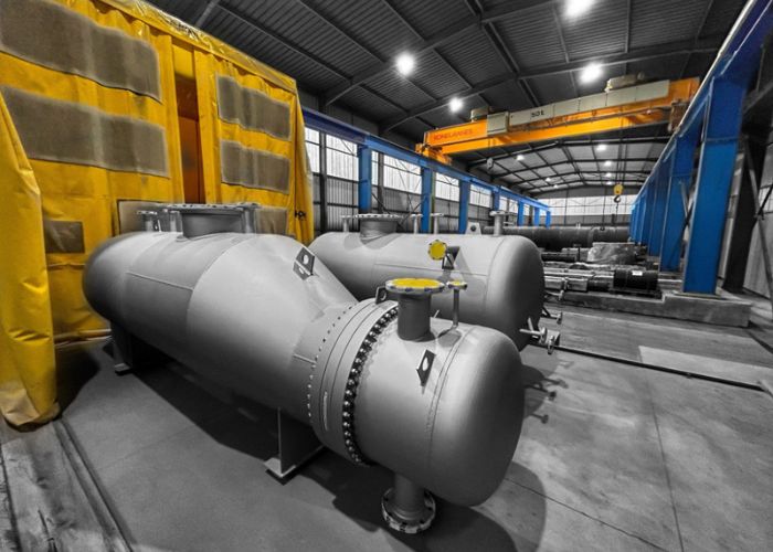
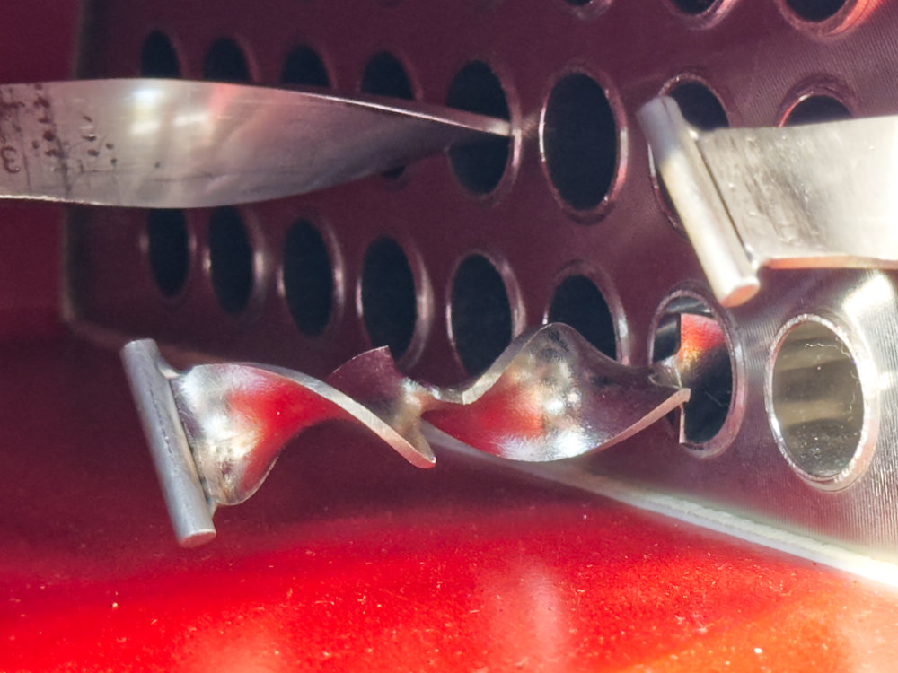
Tube turbulators
Small metallic inserts or specially designed shapes placed inside the tubes to increase fluid turbulence. They improve heat transfer by reducing the thermal boundary layer, without significantly increasing pressure drop.

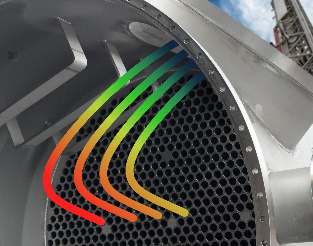
Baffles
Placed inside the shell to direct the flow, increase velocity, and avoid stagnation or dead zones. They improve thermal performance and limit fouling.
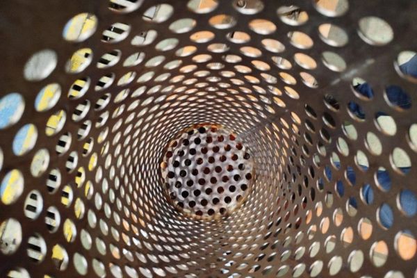
Filters
Integrated into the exchanger, they retain solid impurities present in the fluids before they enter the tube bundle. They protect the internals against fouling or abrasion, ensure stable thermal performance, and extend the equipment's service life.
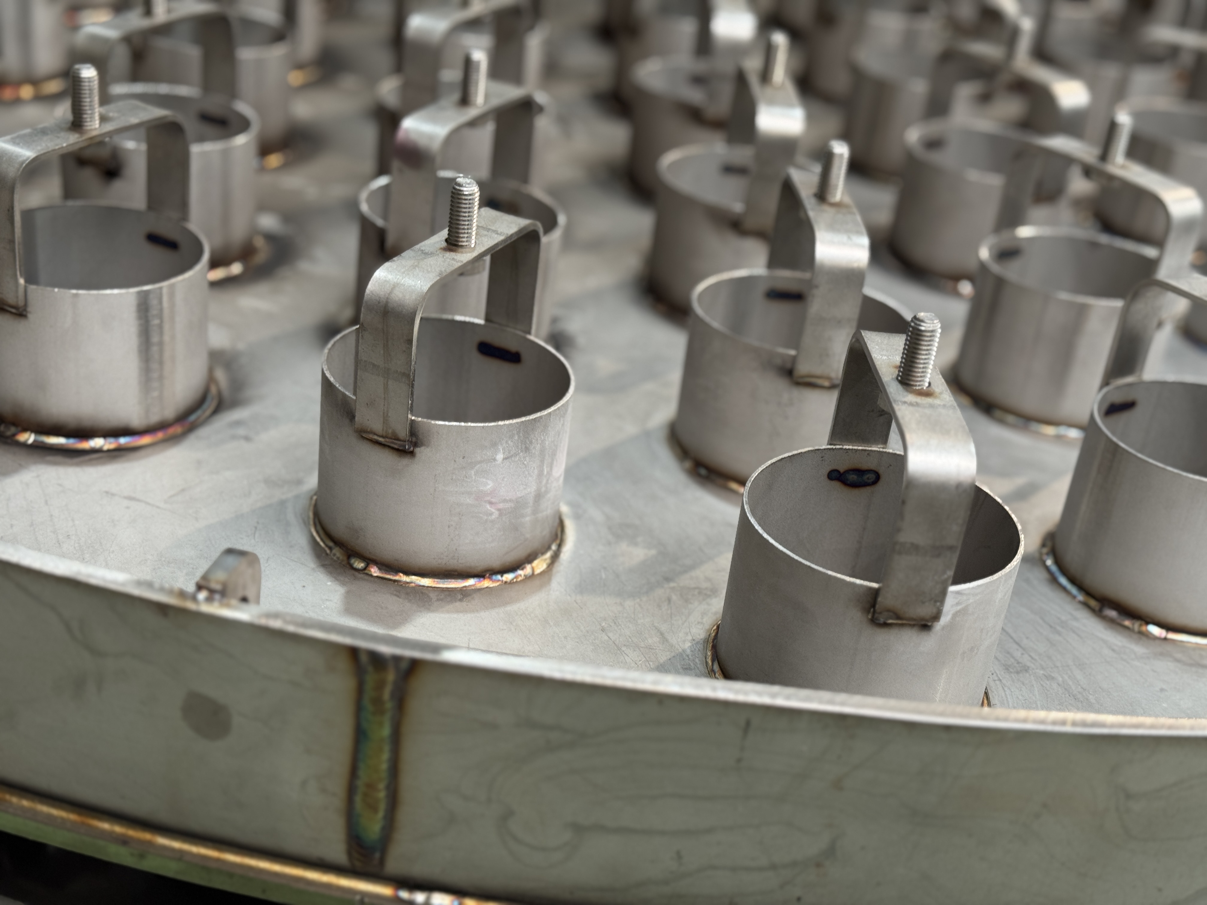
Bubble cap trays
These trays are used in certain columns and other process equipment manufactured by SAG to promote efficient contact between liquid and gas phases. They allow for better distribution and more intense mass transfer, particularly in distillation columns or similar equipment.
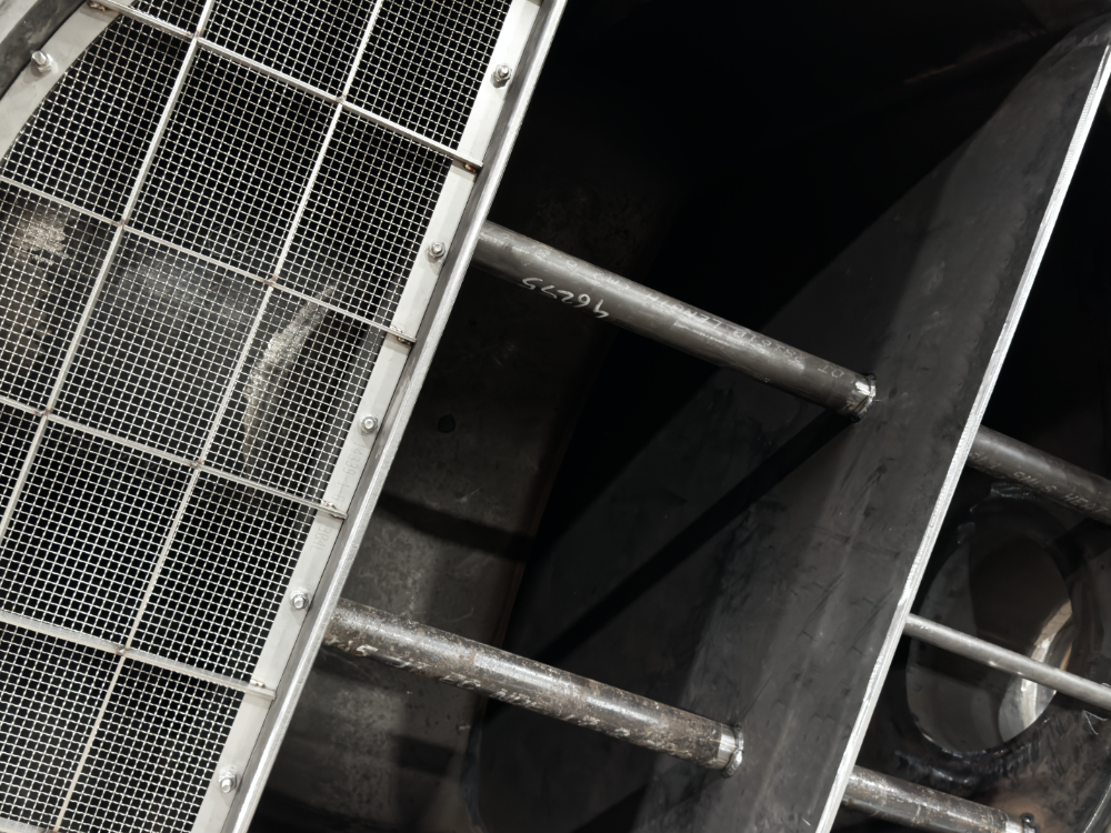
Demisters (mist eliminators)
Placed at the outlet of an exchange or treatment zone, they separate liquid droplets entrained in a gas flow, preventing liquid losses and contamination. They improve gas purity and protect downstream equipment.
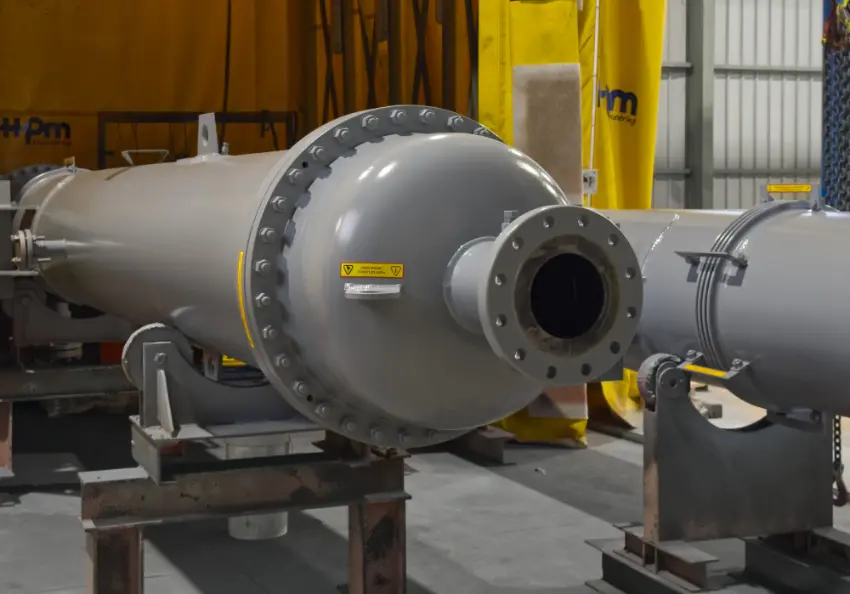
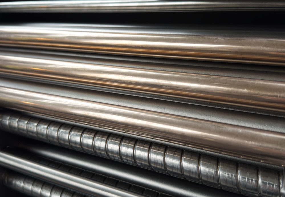
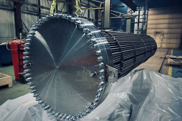
Straight tubes with fixed tubesheets
For steam condensation, e.g. in the chemical industry. Straight tubes with fixed tubesheets are simple to manufacture and install. They suit low-fouling fluids when the temperature difference is moderate.
Removable (floating head) bundle with straight tubes
For cooling syrups or viscous fluids, e.g. in pharmaceuticals or food and beverage. The removable bundle allows mechanical cleaning (CIP) and offers great flexibility for inspection and maintenance.

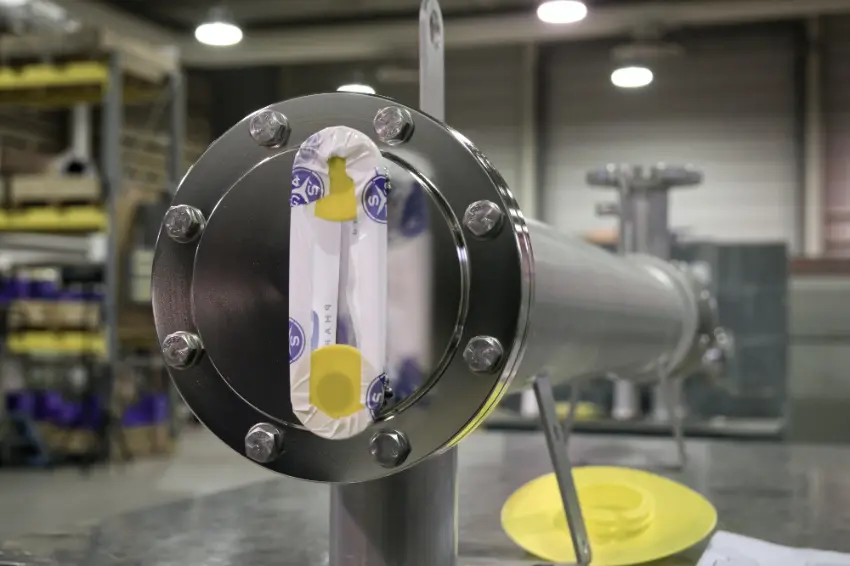
U-tube bundle with transverse baffles and an integrated demister
For cooling high-temperature gases, e.g. in energy or oil & gas. U-tube bundles with baffles and an integrated demister optimize turbulence and droplet separation, while keeping the exchanger compact.
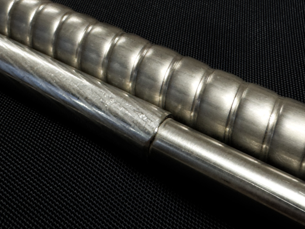
Corrugated tubes with internals (turbulators)
For viscous or low-conductivity fluids, e.g. in chemicals or food and beverage. Corrugated tubes equipped with internal turbulators significantly improve heat transfer. This configuration enhances performance without increasing the size of the exchanger.
Straight tubes with controlled roughness
For applications with strict hygiene requirements, e.g. in pharma. Straight tubes with controlled roughness meet a precise roughness factor (Ra) to facilitate cleaning and limit fluid adhesion. This configuration ensures a process compliant with sanitary standards while remaining robust and durable.
Contact us !
Need to assess the best configuration for your application? Our teams are here to support you, from thermal sizing to design, manufacturing and finishing.
Click here